- 您现在的位置:买卖IC网 > Sheet目录1991 > CS4382A-DQZ (Cirrus Logic Inc)IC DAC 8CH 114DB 192KHZ 48-LQFP
DS618F2
15
CS4382A
SWITCHING CHARACTERISTICS - PCM
(Inputs: Logic 0 = GND, Logic 1 = VLS, CL = 30 pF)
Notes:
14. After powering up, RST should be held low until after the power supplies and clocks are settled.
15. See Table 1 on page 21 for suggested MCLK frequencies.
Parameters
Symbol
Min
Max
Units
RST pin Low Pulse Width
1-
ms
MCLK Frequency
1.024
55.2
MHz
MCLK Duty Cycle
45
55
%
Input Sample Rate - LRCK
Single-speed Mode
Double-speed Mode
Quad-speed Mode
Fs
4
50
100
54
108
216
kHz
LRCK Duty Cycle
45
55
%
SCLK Duty Cycle
45
55
%
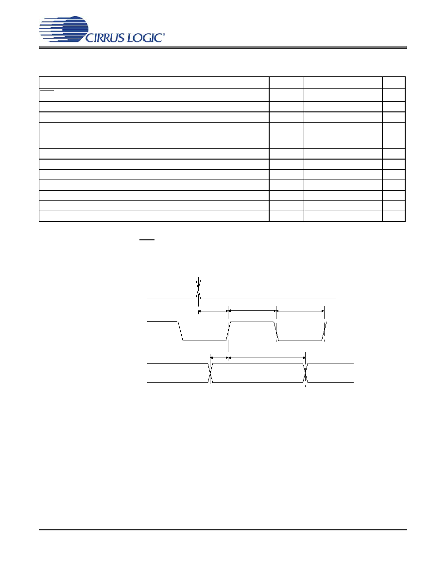
SCLK High Time
tsckh
8-
ns
SCLK Low Time
tsckl
8-
ns
LRCK Edge to SCLK rising edge
tlcks
5-
ns
SDIN Setup Time before SCLK rising edge
tds
3-
ns
SDIN Hold Time after SCLK rising edge
tdh
5-
ns
SDINx
t
ds
SCLK
LRCK
MSB
t
dh
t
sckh
t
sckl
t
lcks
MSB-1
Figure 1. Serial Audio Interface Timing
发布紧急采购,3分钟左右您将得到回复。
相关PDF资料
CS4384-CQZR
IC DAC 8CH 103DB 192KHZ 48-LQFP
CS4385-DQZR
IC DAC 8CH 114DB 192KHZ 48-LQFP
CS4391A-KZZR
IC DAC 24BIT 192KHZ W/VC 20TSSOP
CS4392-KZZ
IC DAC 24BIT 192KHZ W/VC 20TSSOP
CS4397-KSZ
IC DAC 24BIT MULTY STNDRD 28SOIC
CS4398-CZZ
IC DAC 120DB 192KHZ W/VC 28TSSOP
CS43L22-CNZR
IC DAC W/HDPN & SPKR AMPS 40-QFN
CS4461-CZZR
IC ADC PSR FEEDBACK 24-TSSOP
相关代理商/技术参数
CS4382A-DQZR
功能描述:音频数/模转换器 IC IC 114dB 192 kHz 8Chn DAC w/DSD supt. RoHS:否 制造商:Texas Instruments 转换器数量: 分辨率:16 bit 接口类型:I2S, UBS 转换速率: 信噪比:98 dB 工作电源电压:5 V DAC 输出端数量:2 工作温度范围:- 25 C to + 85 C 电源电流:23 mA 安装风格:SMD/SMT 封装 / 箱体:TQFP-32 封装:Reel
CS4382A-EQZ
制造商:CIRRUS 制造商全称:Cirrus Logic 功能描述:114 dB, 192 kHz 8-channel D/A Converter
CS4382A-EQZR
制造商:CIRRUS 制造商全称:Cirrus Logic 功能描述:114 dB, 192 kHz 8-channel D/A Converter
CS4382-KQZ
功能描述:数模转换器- DAC IC 114dB 24-bit 102kHz 8Ch DAC RoHS:否 制造商:Texas Instruments 转换器数量:1 DAC 输出端数量:1 转换速率:2 MSPs 分辨率:16 bit 接口类型:QSPI, SPI, Serial (3-Wire, Microwire) 稳定时间:1 us 最大工作温度:+ 85 C 安装风格:SMD/SMT 封装 / 箱体:SOIC-14 封装:Tube
CS4382-KQZR
功能描述:数模转换器- DAC IC 114dB 24-bit 102kHz 8Ch DAC RoHS:否 制造商:Texas Instruments 转换器数量:1 DAC 输出端数量:1 转换速率:2 MSPs 分辨率:16 bit 接口类型:QSPI, SPI, Serial (3-Wire, Microwire) 稳定时间:1 us 最大工作温度:+ 85 C 安装风格:SMD/SMT 封装 / 箱体:SOIC-14 封装:Tube
CS4383
制造商:CIRRUS 制造商全称:Cirrus Logic 功能描述:114 dB, 192 kHz 8-Channel D/A Converter
CS4383-BQ
制造商:CIRRUS 制造商全称:Cirrus Logic 功能描述:114 dB, 192 kHz 8-Channel D/A Converter
CS4383-KQ
制造商:CIRRUS 制造商全称:Cirrus Logic 功能描述:114 dB, 192 kHz 8-Channel D/A Converter